中国地区询价
 1 (250) 388-3531
 +33 4 86 68 68 10

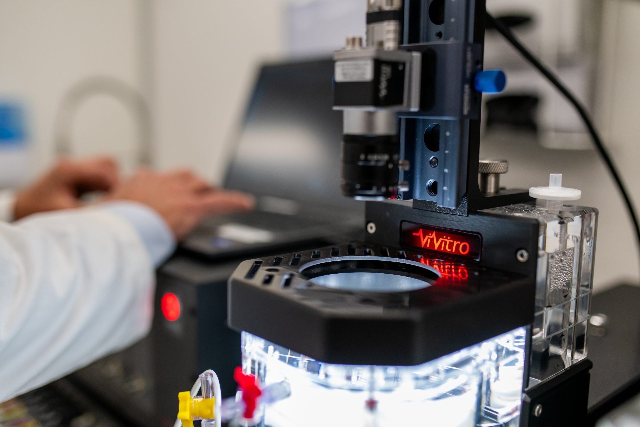
Heart Valve Prosthesis
Accelerated Wear Testing with
On this page:
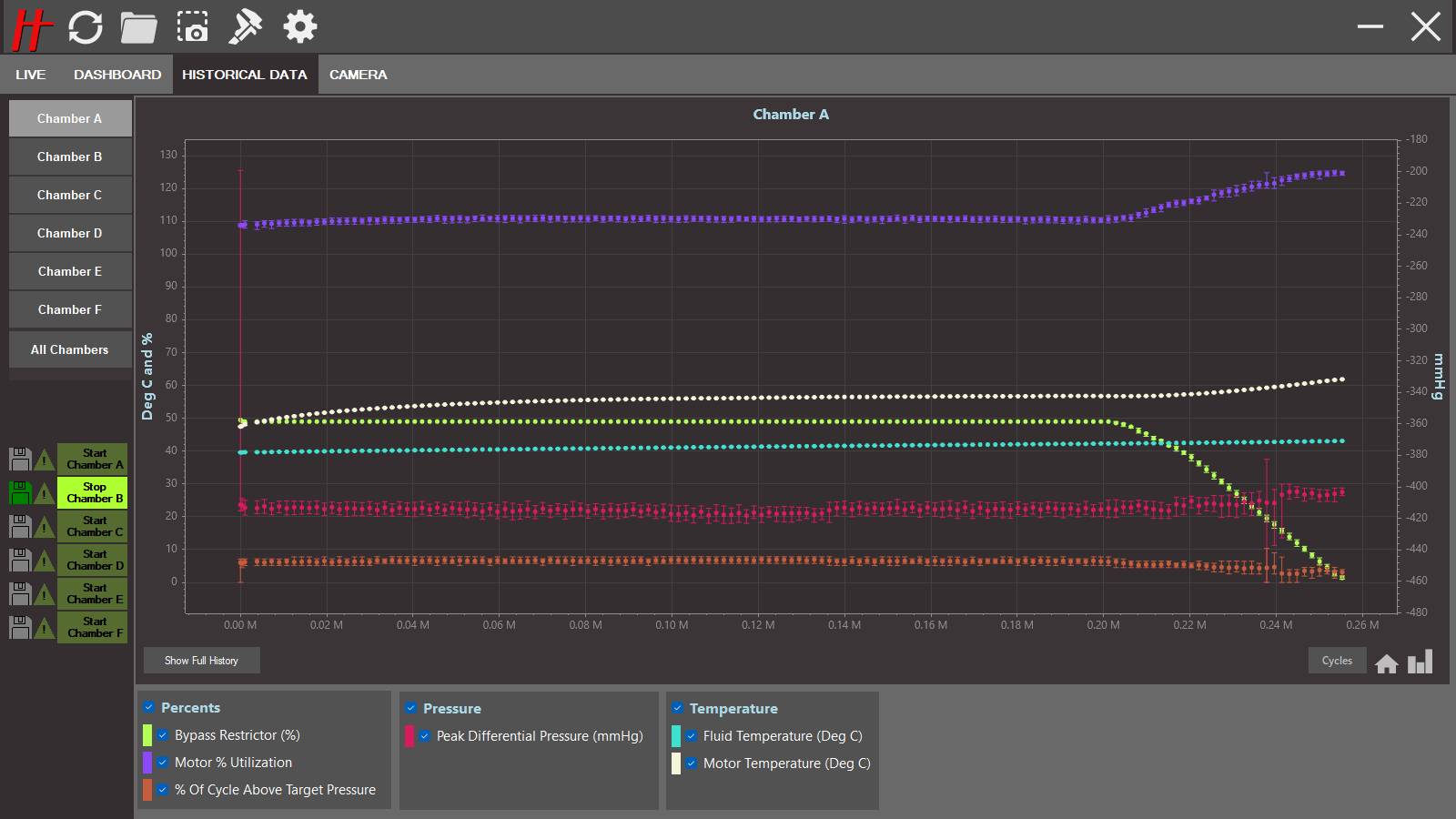
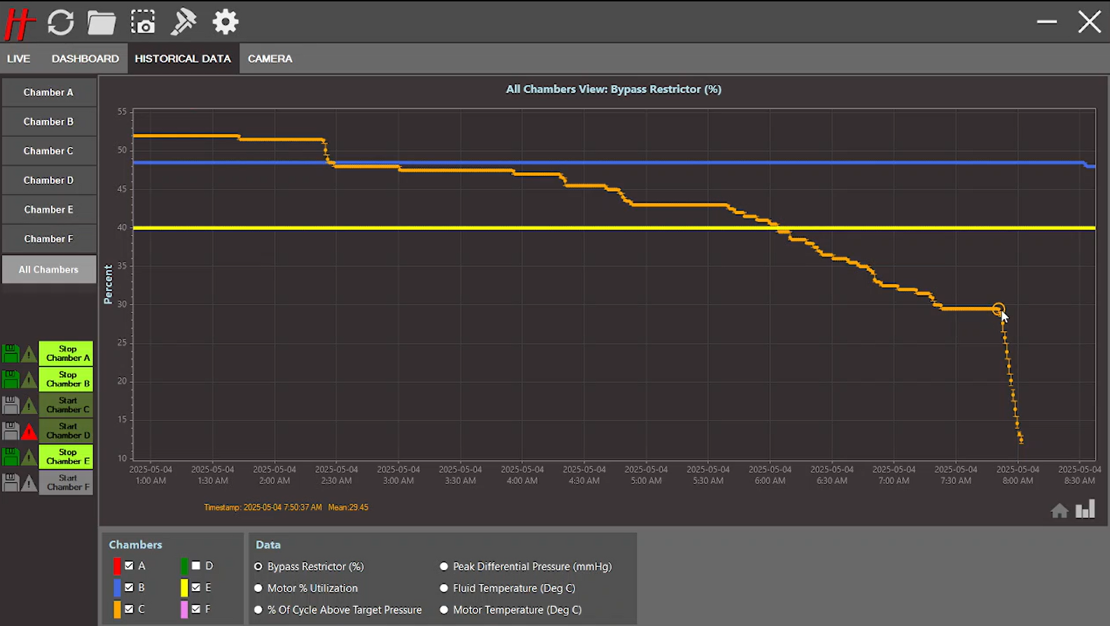
Historical Data View |
Valve Comparison Tool |
Dashboard View
NEW
Historical Data View
VIVITRO LABS AWT-V8 SYSTEM WITH DUAL CONTROL TECHNOLOGY (DCT)™ FIRST AWT TEST SYSTEM TO ALLOW EARLY DETECTION OF VALVE PROSTHESIS FATIGUE FAILURE UNDER CONSTANT LOADING CONDITIONS AT VALVE CLOSURE AND OPENING
FEATURES- Monitor bypass valve behavior
- Monitor system parameters: Bypass valve opening/closing, motor % utilization, motor temp
- Assess operating limits of the system
- Assess the system stability during AWT studies
- Assess system trends and behavior throughout the AWT study
- Assess operating differences and inconsistencies between chambers
- Assist in troubleshooting in system diagnosis to guide repair and maintenance
- Assist in troubleshooting fluid temperature stability issues
- Monitor valve performance parameter: Peak different pressure, % cycle above pressure,
fluid temperature, Bypass valve restriction % opening/closing
Bypass valve opening/closing behavior allows to:
- Pinpoint a failure event on the valve
- Observe continuous subtle degradation of the valve
- Identify a potential cause of odd bypass behaviour, i.e. a bubble in pressure transducer
- Combine long-term views of valve performance parameter to support root cause analysis on events leading to valve failure
- Facilitates inspections of study parameters to confirm study compliance with ISO requirements
- Advance plot navigation tool to assist user to inspect data or region of interest
- Long-term data plots against time or cycle
- Default display set to 24 hrs and auto-refreshes to show the most recent data trends
- Short term view to display most recent data with higher resolution – up to 5 days
- Long term view to display historical study data with lower resolution – from beginning of logging session
- Conveniently analyze long terms trends of large data sets without requiring users to post-process large amounts of data
SPECIFICATIONS
Duration of Recent History View: Up to 5 Days
Duration of Full History View: Entire test duration
Number of Chambers Supported: 6
Number of Parameters Shown: up to 6
Parameters available for display: peak differential, % of cycle meeting target pressure, fluid temperature, motor temperature, motor % utilization, bypass valve % position
NEW
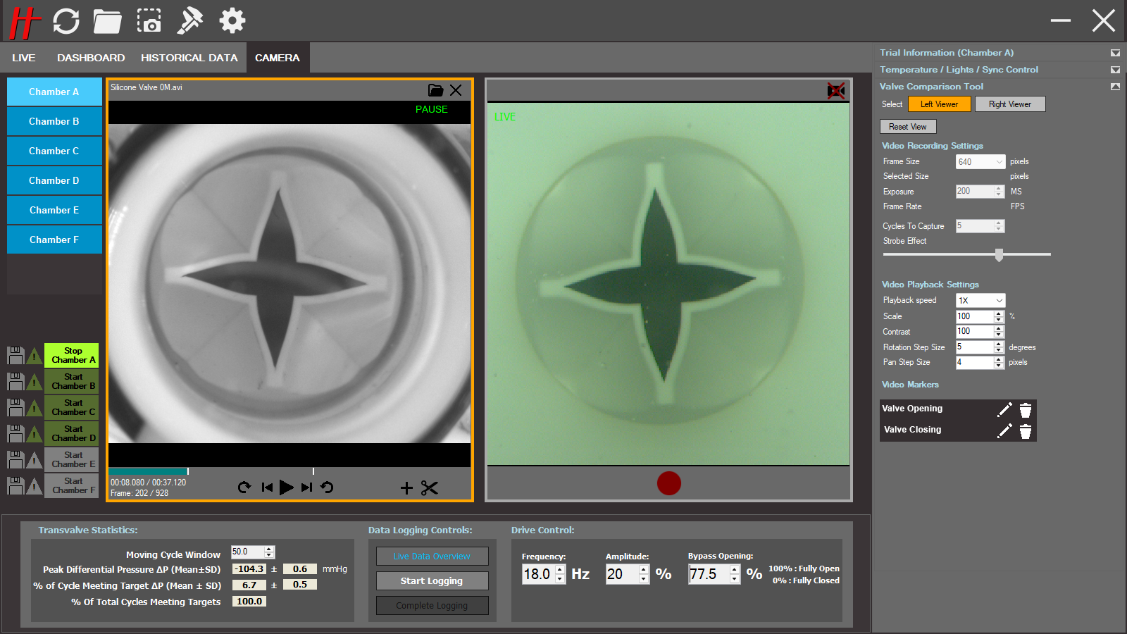
Valve Comparison Tool
VIVITRO LABS AWT-V8 SYSTEM WITH DUAL CONTROL TECHNOLOGY (DCT)™ FIRST AWT TEST SYSTEM TO INTEGRATE SIDE-BY-SIDE LIVE KINEMATICS ASSESSMENT OF HEART VALVE PROSTHESIS DURING FATIGUE STUDIES
FEATURES
The ViVitro Labs AWT-V8 with DCT™ is a highly integrated tools specifically designed to ease valve inspection during AWT studies. The tool is made of 4 indissociable parts- High Speed High Resolution 2.51 MP Camera with a 25 mm Lense
- Integrated High Speed Camera Valve Comparison software interface
- Adjustable intensity annular LED light for maximum high-speed imaging luminosity with minimal reflection impact
- Micrometric Rail Support System:
- for repeatable high-speed camera positioning, increased image stability and reliability between inspection cycles
- for easy and quick repeatable positioning between test modules
System features
- High Speed Camera with AWT system auto recognition - Uninterrupted camera recognition for live stream from chamber to chamber, even when closing the view.
- Software integrated High Speed Camera interface designed for video live streaming during valve tuning
- AWT system control parameters and test sample health statistics visible and accessible during live streaming and recorded video playing
- Automatic AWT test module visual identification upon video capture to minimize error on test sample selection – flashing light
- Adjustable intensity annular LED light for maximum high-speed imaging luminosity with minimal reflection impact
- Dedicated Micrometric Rail Support System for repeatable high-speed camera positioning, increased image stability and reliability between inspection cycles
- Player features
- Standard functions of any video player (play, pause, etc.).
- Allows opening and closing any recorded video segment from various test systems
- Play back settings (speed, scale, contrast, rotation and pan size)
- Video autoloop for continuous and uninterrupted valve cycle inspection
- Video navigation (step frame by frame) leveraging the maximum precision available in the video to determine the optimum valve opening position
- Video rotation and pan settings for side-by-side valve comparison to facilitate precise test sample analysis
- Video markers to identify specific frames in relation to valve position
- Labelled video makers to identify specific events in relation to valve kinematics
- Video clipping for isolating specific valve cycles
- Video saving protocol for traceability and classification (default or user define)
- Resetting function for all user defined video parameters
- Live stream features
- Virtual strobe effect to slow down live stream for ease of inspection
- Adjustable frame size to optimize valve inspection capabilities
- User selectable frame size to optimize and facilitate valve inspection
- Video setting reproducibility for convenient replication of recorded video settings to accelerate livestream video configuration
- Recording function features
- Easy identification of targeted chamber during live recordings to reduce user error and AWT chamber confusion
- Metadata for AWT video segment captured with the file for easy reproduction (frame size, exposure recorded date, trial information, recording settings)
- Predefine number of cycles selection for efficient and consistent video capture and to minimize file size.
- Embedded export settings to allow users to visualize HS events in slow motion
- Auto naming video files based on AWT study information for improved traceability
- Export in a universal MP4 format for compatibility
SPECIFICATIONS
High Speed Camera:
Micrometric Rail Support System:
Output file formats: MP4
Input file formats: MP4, AVI, FLV, MOV, MKV
| Standard file size examples - Assuming 5 Cycles at 20Hz | ||
| Frame Size | FPS | File Size |
|---|---|---|
| 480x480px | 818 | 4.87MB |
| 544x544px | 736 | 6.06MB |
| 641x641px | 641 | 8.02MB |
| 736x736px | 538 | 10.00MB |
NEW
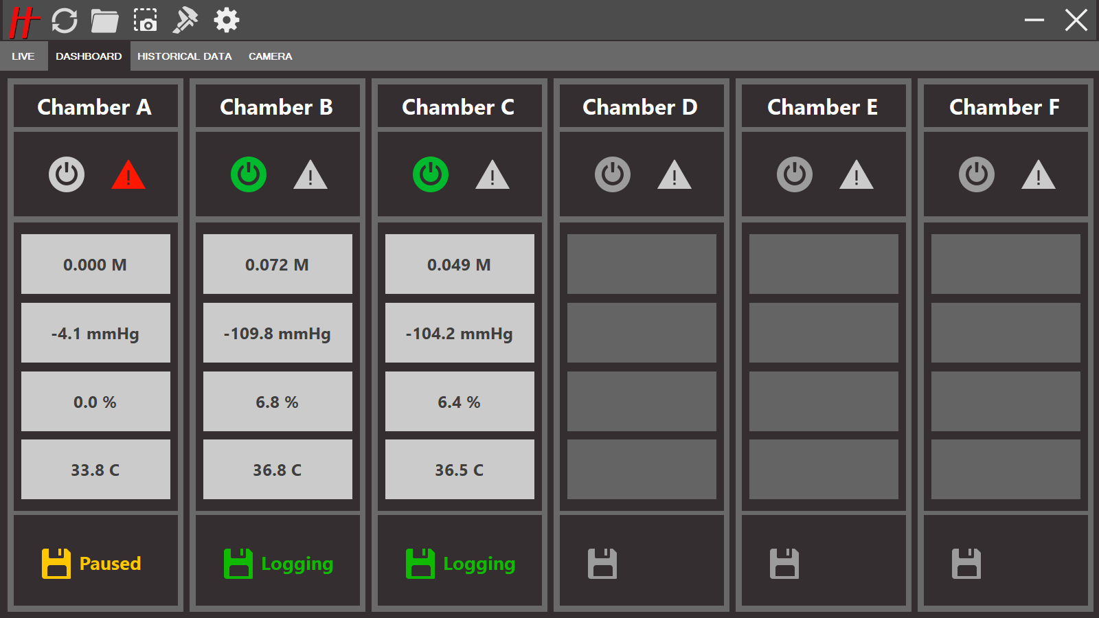
Dashboard View
VIVITRO LABS AWT-V8 SYSTEM WITH DUAL CONTROL TECHNOLOGY (DCT)™ FIRST AWT TEST SYSTEM TO ENABLE SMART AT-A-GLANCE OVERVIEW OF THE STATUS OF MULTIPLE AWT TEST MODULES
FEATURES
- Instantly provides a global view of current readings against targets for each chamber
- Continuously monitors system measurements and conveniently displays set points or targets for 4 of the key measurements for all chambers connected to an AWT system
- Key measurements including passing cycles, peak differential pressure, % of cycles meeting target pressure, and fluid temperature
- Instantly provides a global view of each standalone test module status
- Continuously monitors individual chamber health by providing information on motor status (running or stopped). Also provides information about the test logging status (inactive, paused, logging).
- Provides system faults and errors with a warning indicator which can be clicked to display messages
- Instantly flags users when study and system alarms are triggered
- View system information at a distance to facilitate system monitoring as a whole.
- Instantly provides passing cycle count for each module
- Displays current passing cycle count for the study against the target.
- Leverages advanced algorithms to detect the pressure waveform compliance to ISO 5840 passing criteria.
- Provide clarity on study duration estimate by displaying the progress of the study against total cycle count target for each valve.
- Instantly provides peak differential pressure reading for each chamber
- Displays real time peak differential for each valve to allow user to assess valve loading conditions at any time during the study
- Identifies the pressure target for each valve when running each chamber under different loading conditions and protocols
- Instantly flags users when each chamber pressure is not meeting target (5% rule)
- Leverages advanced algorithms to detect the pressure waveform compliance to ISO 5840 passing criteria.
- Digital readout and color coding (red) conveys real-time attainment of pressure target and alerts user on the status of the chamber.
- Instantly flags users when chamber temperature is out of range
- Digital readout and color coding (red) conveys real-time attainment of temperature target +/- 2°C per ISO 5840 and alerts user when out of range
SPECIFICATIONS
Number of Parameters Shown: 4
Number of Chambers: Up to 6 (up to total 24 parameters)
Live Numeric Parameters Displayed: Number of Passed Cycles, Peak Differential Pressure, Percent of Cycle Above Target Pressure, Fluid Temperature
Parameter Color Indicators: Red for outside of acceptable ranges for 5% Rule and Temperature
Individual Chamber Running State Indicator: Off, On
Data Logging States: Off, Paused, Active
Error Indicator States: No Warnings, New Warning, Viewed Warning